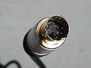
A standard 4-pin S-Video cable connector, with each signal pin paired with its own ground pin.
Separate video, abbreviated S-Video and also known as Y/C (or erroneously, S-VHS and "super video") is an analog video signal that carries the video data as two separate signals (brightness and color), unlike composite video which carries the entire set of signals in one signal line. S-Video, as most commonly implemented, carries high-bandwidth 480i or 576i resolution video, i.e. standard definition video.It also has audio.
Overview

Y/C signal comparison between composite (a) and S-video (b).
The luminance (Y; greyscale) signal and modulated chrominance (C; colour) (A; audio)information are carried on separate synchronized signal/ground pairs.
In composite video, the luminance signal is low-pass filtered to prevent crosstalk between high-frequency luminance information and the color subcarrier. S-Video separates the two, and detrimental low-pass filtering is unnecessary. This increases bandwidth for the luminance information, and also subdues the color crosstalk problem. The infamous dot crawl is eliminated. This means that S-Video leaves more information from the original video intact, thus having a much-improved image reproduction compared to composite video.
Due to the separation of the video into brightness and colour components, S-Video is sometimes considered a type of component video signal, although it is also the most inferior of them, quality-wise, being far surpassed by the more complex component video schemes (like RGB). What differentiates S-Video from these higher component video schemes is that S-Video carries the colour information as one signal. This means that the colours have to be encoded in some way, and as such NTSC, PAL and SECAM signals are all decidedly different through S-Video. Thus, for full compatibility the used devices not only have to be S-Video compatible but also compatible in terms of colour encoding.
Connector
Today, S-Video signals are generally connected using 4 pin mini-DIN connectors using a 75 ohm termination impedance. Apart from the impedance requirement, these cables are equivalent to regular mini-DIN cables (like Apple's ADB); these cables can be used for S-Video transfer if no other cable is available, but picture quality may not be as good. Due to the wide use of S-Video connections for DVD players, S-Video cables are fairly inexpensive compared to component or digital connector cables, and are routinely available in places where the higher-bandwidth cables are not.
The mini-DIN pins, being weak, sometimes bend. This can result in the loss of color, or other corruption (or loss) in the signal. A bent pin can be forced back into shape, but this carries the risk of further damage, or even the pin breaking off.
Before the mini-DIN plug became standard, S-Video signals were often carried through different types of plugs. For example, the Commodore 64 home computer of the 1980s, one of the first widely available devices to feature S-Video output, used an 8-pin DIN connector on the computer end and a pair of RCA plugs on the monitor end. The S-Video connector is the most common video-out connector on laptop computers, however many devices with S-Video outputs also have composite outputs.
S-Video and audio (mono) can be transferred through SCART connections as well. However, it was not part of the original SCART standard, and not every SCART-compatible device supports it for this reason. Also, S-Video and RGB are mutually exclusive through SCART, due to the S-Video implementation using the pins allocated for RGB. Most SCART-equipped televisions or VCRs (and almost all of the older ones) do not actually support S-Video, resulting in a black-and-white picture if such a connection is attempted, as only the luminance signal portion is usable. Generally, a black-and-white picture in itself can also be a sign of incompatible colour encoding--for example NTSC material viewed through a PAL-only device.
A hack exists to possibly attain color on devices that do not support S-Video through SCART. This is done via joining the pins 15 and 20 in the SCART connector (either directly or using a 470pF capacitor), and may not yield optimal results.
A similar hack also allows color. This connects the Y and C (3 and 4) pins on the S-Video connector.
Specifications
Connector
Pin numbers (looking at socket):
Image:MiniDIN-5 Connector Pinout.svg
Pin assignments
| Pin |
Name |
Function |
| 1 |
GND |
Floor or Ground (Y) |
| 2 |
GND |
Ground (C) |
| 3 |
Y |
Intensity (Luminance) |
| 4 |
C |
Color (Chrominance) |
| 5 |
A |
Audio (A) |
Usage
S-Video is commonly used in USA, Canada, Australia, and Japan, found there on consumer TVs, DVD players, high-end video cassette recorders, Digital TV receivers, DVRs, and game consoles. Almost all TV-out connectors on graphics cards are S-Video, even in Europe, where the standard failed to make a significant impact due to the preference for the higher-quality RGB signal provided by SCART.
Because it is very simple to convert S-Video to composite signal (just the logical merging of the two through a filter capacitor is required), many electronics retailers offer converter adaptors for signal conversion. No conversion will improve image quality, but will allow connecting to otherwise-incompatible devices. Converting composite signal to S-Video is a little harder.
Due to a lack of bandwidth, S-Video connections are generally not considered suitable for high-definition video signals. As a result, HD sources are generally connected to a monitor by way of analog component video or wideband digital methods (usually HDMI or DVI).
The situation with VCRs is a bit unusual; the common S-Video connector was designed for Super VHS VCRs as a high-bandwidth video connection, and has been used for the same purpose on a great number of other consumer devices, coming into greatest prominence with the rise of the DVD format. Many digital, Hi-8, and S-VHS-C camcorders support S-Video out as well, but standard VHS VCRs do not put out a high enough resolution signal to saturate an S-Video connection, and therefore most such units, even those in combination units with DVD players (which commonly use S-Video or component outputs), require the output from the VHS deck to go through a composite video or RF connection.
